Power Management Integrated Circuit (PMIC) Guide
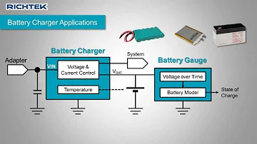
How to Select a Power Management Component for Your Application
Catalog |
I Basic definition
Power Management Integrated Circuits (PMIC) is a chip that is responsible for the conversion, distribution, detection, and other power management of electrical energy in electronic equipment systems. It is mainly responsible for converting the source voltage and current into power that can be used by microprocessors, sensors, and other loads.
II PMIC Types
The relatively wide range of power management includes power conversion (DC-DC, AC-DC, and DC -AC), power distribution and detection, and systems that combine power conversion and power management. Accordingly, the classification of power management integrated circuits includes these aspects, such as linear power supply chips, voltage reference chips, switching power supply chips. LCD driver chips, LED driver chips, voltage detection chips, battery charging management chips, gate drivers, load switches, wide bandgap switches, etc.
(1) Voltage regulator chips
1) Linear regulator chips
(I) Traditional linear regulator chip
Linear regulators convert the input voltage (VI) to different output voltages (VO) using a linear component (i.e. resistive component) to regulate the output voltage VO. Below are the application circuits for linear regulators.
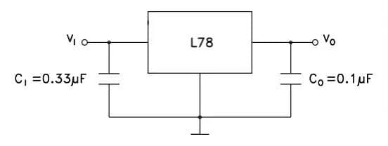
Figure 1. application circuits for linear regulators
(II) low dropout linear regulator chip
For linear regulators, an important type is a low dropout (LDO) linear regulator. It can continuously output a stable voltage when the difference between the input voltage (VIN) and the output voltage (VOUT) is very small.
The four key elements of LDO are:
- Dropout
- Noise
- Power Supply Rejection Ratio (PSRR)
- Static current Iq
(III) Advantages and disadvantages of linear regulator chips
Linear regulators are called "linear regulators" because the relationship between input and output is linear during operation. Because the input and output are connected in series with the control element, sometimes also called "series regulator".
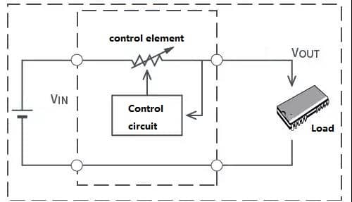
Figure 2. Linear Regulator Circuit
Linear regulator chips are generally bucked by the control element, so the greater the voltage difference between input and output (the degree of bucking), the greater the losses and the lower the efficiency. Therefore, it is suitable for low-power power supplies.
Advantages | Disadvantages |
Simple circuit | Low efficiency |
Few external components | High heat generation |
Low noise level | Buck converter only |
2) Switching regulator
Switching regulators convert VIN to a different VOUT through a switching element and use an external inductor and capacitor to stabilize the output voltage VOUT. Switching regulators are generally more efficient and support higher output currents than linear regulators. However, there is still ripple or switching noise after the output has been regulated, which remains even after filtering.
I) Types of switching regulator chips
Power supply device to lower the voltage | Buck converter, Buck converter, Step-down converter |
Power supply device to increase voltage | Boost converter, Boost converter, Step-up converter |
Power supply devices that increase or decrease voltage | Buck-up converters, Buck-boost converters |
Power supply device that generates negative voltage | Negative voltage converter, Inverting converter, Inverting converter |
a) Buck converter chips
Buck type step-down switching regulator is the one whose input voltage is higher than the output voltage, and the conversion principle is shown in the following figure.
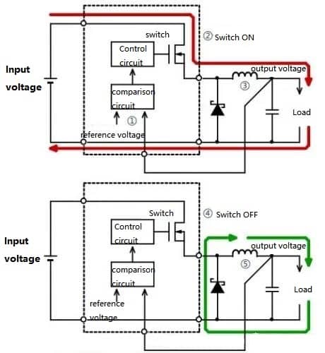
Figure 3. Buck-type step-down switching regulator conversion principle

Figure 4
①Detect the output voltage and compare it with the reference voltage.
②When it is lower than the set output voltage, the switch is ON and the current direction flows according to the red arrow.
③The inductor stores magnetic energy.
④When the output voltage is higher than the set voltage, the switch is turned OFF and the current direction flows according to the green arrow.
⑤ The inductor converts the stored magnetic energy into the current for the load output and then returns it to the inductor.
⑥When the magnetic energy of the inductor disappears and the output voltage starts to drop, the switch turns ON again.
By controlling the turn-off and turn-on time of the switch, a stable output voltage can be obtained.
Example of buck converter circuit application:

Figure 5. Buck Converter Circuit Application Examples
b) Boost converter chip
The boost circuit is one of the six basic chopper circuits, a switching DC boost circuit, which can make the output voltage higher than the input voltage. It is mainly used in DC motor drives, single-phase power factor correction (PFC) circuits, and other AC/DC power supplies.
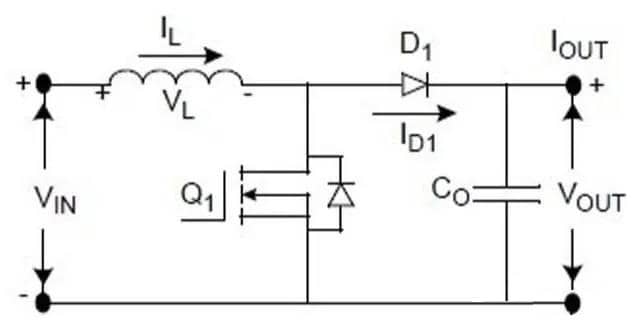
Figure 6. boost converter circuit
Boost converter circuit application examples:
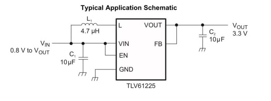
Figure 7. Boost Converter Circuit Application Example
c) Buck-boost converter chip
Buck-boost converter is a DC-DC converter whose output voltage magnitude can be greater than the input voltage or less than the input voltage. Buck-boost converters are equivalent to revertant converters, but with a single inductor instead of a transformer.
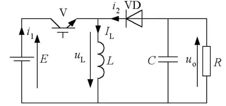
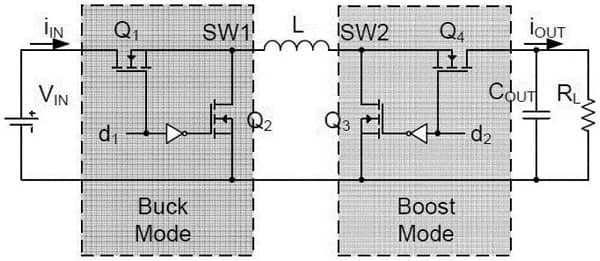
Figure 8. buck-boost converter
Examples of buck-boost converter circuit applications.

Figure 9. Buck-Boost Converter Circuit Application Example
d) Negative voltage converter chips
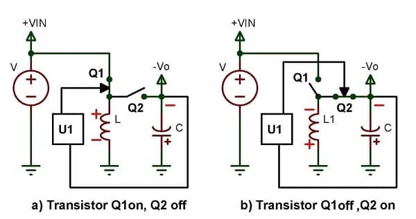
Figure 10. Negative Voltage Converter Circuit
Negative voltage converter circuit application examples.

Figure 11. Negative Voltage Converter Circuit Application Example
II) Advantages and disadvantages of switching regulator chips
The switching regulator chip turns on the switching element (MOSFET) and supplies power from the input to the output until the output voltage reaches the desired voltage. Once the output voltage reaches the specified value, the switching element is turned off and no more input power is consumed. By repeating this action at high speed, the switching element regulates the output voltage to the specified value.
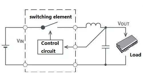
Figure 12. switching regulator circuit
Advantages | Disadvantages |
High efficiency | Many external components |
Low heat generation | Difficult to design |
Boost/buck/negative voltage conversion | High noise level |
(2) Voltage reference chip
Within the rated operating current range, the accuracy of the reference voltage source device (voltage value deviation, drift, current regulation rate, and other indicator parameters) is much better than the ordinary Zener regulator diode or three-terminal regulator, so it is used in the need for high-precision reference voltage as a reference voltage. It is generally used for A/D, D / A, and high-precision voltage sources. Some voltage monitoring circuits also use the reference voltage source.
Commonly used TL431 voltage reference chip application examples.

Figure 13. TL431 voltage reference chip application example
(3) Voltage detection chip
Voltage detection chip circuit application examples.
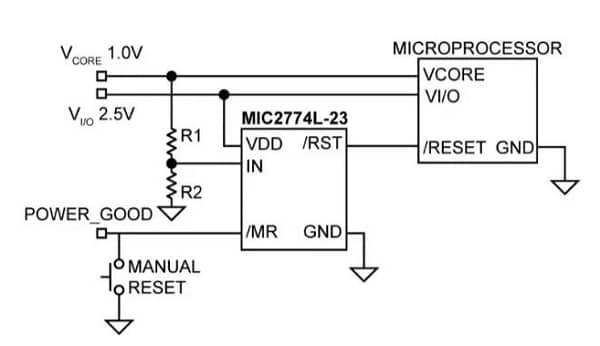
Figure 14. Application example of voltage detection chip circuit
(4) Driver chips
Commonly used LED driver chip circuit application examples.
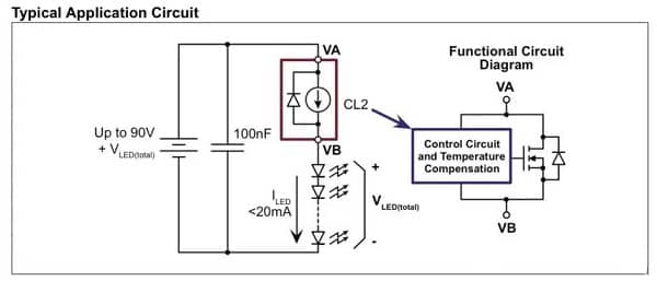
Figure 15. Application example of LED driver chip circuit
Commonly used digital display driver chip circuit application examples.
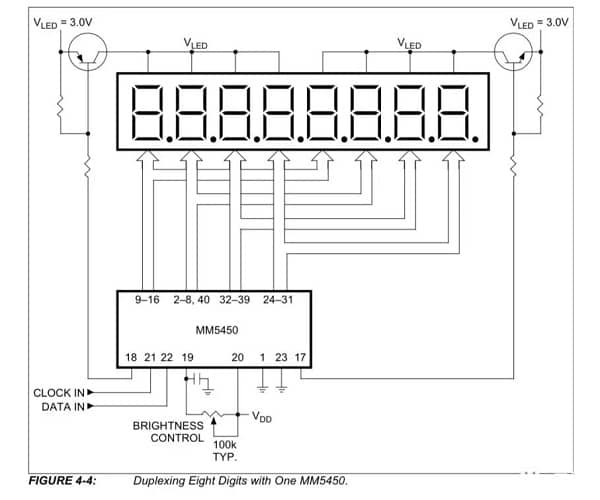
Figure 16. Digital display driver chip circuit application example
Commonly used gate driver chip circuit application examples.
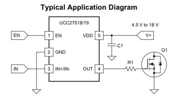
Figure 17. Application example of gate driver chip circuit
III Application scope
The application range of power management integrated circuits is very wide. The development of power management integrated circuits is important to improve the performance of the whole machine. The choice of a power management integrated circuit is directly related to the needs of the system, and the development of digital power management integrated circuit still needs to cross the cost barrier.
In today's world, people's life is a moment that can not be separated from electronic equipment. Power management integrated circuit in the electronic equipment system is responsible for the transformation of electrical energy, distribution, detection, and other electrical energy management responsibilities. Power management integrated circuit is indispensable to the electronic system, and their performance has a direct impact on the performance of the machine.
IV Future trends
Power management integrated circuit has a bright future. Through the development of new processes, packaging and circuit design technologies, there will be more outstanding performance of the device is born, they can improve power density, extend battery life, reduce electromagnetic interference, enhance power and signal integrity and improve system security, to help engineers around the world to achieve innovation.
1.What is PMIC used for?
A power management integrated circuit (PMIC) is used to manage power on an electronic devices or in modules on devices that may have a range of voltages. The PMIC manages battery power charging and sleep modes, DC-to-DC conversion, scaling of voltages down or up, among others.
2.What does PMIC mean in electronics?
Power management ICs (PMICs) are integrated circuits that include multiple power rails and power management functions within a single chip.
3.What is PMIC voltage regulator?
Products in the DC-DC switching regulator PMIC (Power Management Integrated Circuit) family are component-level devices used in applications requiring stabilization of a DC input voltage and/or transformation thereof to an output voltage of different magnitude.
4.What is meant by power management?
Power management is a feature of some electrical appliances, especially copiers, computers, computer CPUs, computer GPUs and computer peripherals such as monitors and printers, that turns off the power or switches the system to a low-power state when inactive.
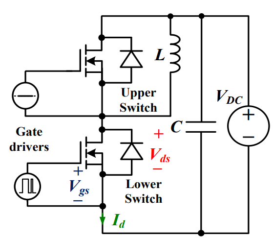 Discovering New and Advanced Methodology for Determining the Dynamic Characterization of Wide Bandgap DevicesSaumitra Jagdale15 March 20242375
For a long era, silicon has stood out as the primary material for fabricating electronic devices due to its affordability, moderate efficiency, and performance capabilities. Despite its widespread use, silicon faces several limitations that render it unsuitable for applications involving high power and elevated temperatures. As technological advancements continue and the industry demands enhanced efficiency from devices, these limitations become increasingly vivid. In the quest for electronic devices that are more potent, efficient, and compact, wide bandgap materials are emerging as a dominant player. Their superiority over silicon in crucial aspects such as efficiency, higher junction temperatures, power density, thinner drift regions, and faster switching speeds positions them as the preferred materials for the future of power electronics.
Read More A Comprehensive Guide to FPGA Development BoardsUTMEL11 September 202510060
This comprehensive guide will take you on a journey through the fascinating world of FPGA development boards. We’ll explore what they are, how they differ from microcontrollers, and most importantly, how to choose the perfect board for your needs. Whether you’re a seasoned engineer or a curious hobbyist, prepare to unlock new possibilities in hardware design and accelerate your projects. We’ll cover everything from budget-friendly options to specialized boards for image processing, delve into popular learning paths, and even provide insights into essential software like Vivado. By the end of this article, you’ll have a clear roadmap to navigate the FPGA landscape and make informed decisions for your next groundbreaking endeavor.
Read More Applications of FPGAs in Artificial Intelligence: A Comprehensive GuideUTMEL29 August 20252585
This comprehensive guide explores FPGAs as powerful AI accelerators that offer distinct advantages over traditional GPUs and CPUs. FPGAs provide reconfigurable hardware that can be customized for specific AI workloads, delivering superior energy efficiency, ultra-low latency, and deterministic performance—particularly valuable for edge AI applications. While GPUs excel at parallel processing for training, FPGAs shine in inference tasks through their adaptability and power optimization. The document covers practical implementation challenges, including development complexity and resource constraints, while highlighting solutions like High-Level Synthesis tools and vendor-specific AI development suites from Intel and AMD/Xilinx. Real-world applications span telecommunications, healthcare, autonomous vehicles, and financial services, demonstrating FPGAs' versatility in mission-critical systems requiring real-time processing and minimal power consumption.
Read More 800G Optical Transceivers: The Guide for AI Data CentersUTMEL24 December 20251653
The complete guide to 800G Optical Transceiver standards (QSFP-DD vs. OSFP). Overcome supply shortages and scale your AI data center with Utmel Electronic.
Read More Xilinx FPGAs: From Getting Started to Advanced Application DevelopmentUTMEL09 September 20253459
This guide is your comprehensive roadmap to understanding and mastering the world of Xilinx FPGA technology. From selecting your first board to deploying advanced AI applications, we'll cover everything you need to know to unlock the potential of these remarkable devices. The global FPGA market is on a significant growth trajectory, expected to expand from USD 8.37 billion in 2025 to USD 17.53 billion by 2035. This surge is fueled by the relentless demand for high-performance, adaptable computing in everything from 5G networks and data centers to autonomous vehicles and the Internet of Things (IoT). This guide will walk you through the key concepts, tools, and products in the Xilinx ecosystem, ensuring you're well-equipped to be a part of this technological revolution.
Read More
Subscribe to Utmel !
![ACPL-337J-500E]() ACPL-337J-500E
ACPL-337J-500EBroadcom Limited
![ADUM3223BRZ-RL7]() ADUM3223BRZ-RL7
ADUM3223BRZ-RL7Analog Devices Inc.
![AD5522JSVDZ]() AD5522JSVDZ
AD5522JSVDZAnalog Devices Inc.
![ACPL-W343-500E]() ACPL-W343-500E
ACPL-W343-500EBroadcom Limited
![HCS515-I/SL]() HCS515-I/SL
HCS515-I/SLMicrochip Technology
![FOD3150S]() FOD3150S
FOD3150SON Semiconductor
![1EDI20I12AFXUMA1]() 1EDI20I12AFXUMA1
1EDI20I12AFXUMA1Infineon Technologies
![AT88SC0104CA-SH-T]() AT88SC0104CA-SH-T
AT88SC0104CA-SH-TMicrochip Technology
![SI8233BD-D-IS]() SI8233BD-D-IS
SI8233BD-D-ISSilicon Labs
![FOD3180SD]() FOD3180SD
FOD3180SDON Semiconductor


